In our last article on hot gas reheat coils, we looked at the basic function of hot gas reheat coils and some common methods used to integrate them into a system. In this article, we'll look at some best practices when running hot gas reheat coil selections within Enterprise, SRC's coil selection software. For this exercise, we used a theoretical hot gas reheat coil to explain the coil selection process for hot gas reheat coils using the hot gas and parallel condensing methods.
Because of its rarity and the likelihood that the performance requirement can be met using one of the other configurations, we have not included selection best practices for the warm liquid method. But, if you find yourself working on an application that may be well suited for that approach, feel free to contact us directly and we’d be happy to take a look.
The specifications of the theoretical coil used for this exercise can be found below.
Air flow: 7,880 SCFM
Air pressure: 14.696 PSIA
EAT: 55F
LAT: 80F
Entering fluid temp: 188F
Leaving fluid temp: 90F
Refrigerant: R-410A
The resulting capacity from these inputs indicates that our HGRH coil will need to perform at 214,730 Btu./hr.
This is the most common HGRH coil configuration method that we come across and is well-suited for most standard applications.
After entering the thermal requirements above, you’ll want to run this selection as a fluid coil. This is the primary difference between rating a HGRH coil vs. rating ‘standard’ coils in a system. For the coil’s construction, we’ll use ½” OD tube, a reasonable starting point for many fluid coil applications. 3/8” may be viable as well, but for this exercise, we’ll stick with a basic 1/2” copper tube .0016” wall and aluminum fins – in this case 10 fins per inch with a corrugated pattern. The coil’s dimensions will be 45" x 60".
When choosing the fluid type, select ‘other.’ From there, you’ll want to enter the ‘fluid type’ as R-410A, and then enter its thermal properties. This information is readily available in tools such as RefProp if that’s available to you. If not, there are other, open-source programs we can refer you to. Once the thermal data for R-410A is entered, the tube-side requirements will look like the image below.
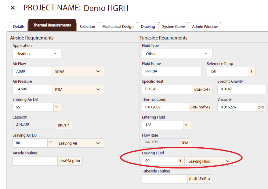
Note: it’s important to ensure that your flow rate is driven by the application’s leaving fluid temperature (as opposed to the inverse) to avoid condensing within the coil. In this application, a higher flow rate is desirable.
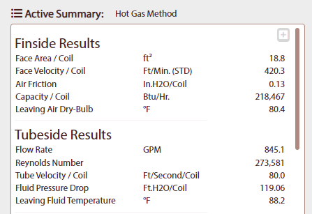
Run the selection, and if the results are reasonable for your application, you’re all set.
Again, deciding on a HGRH coil design method largely comes down to individual preference. But by and large, the parallel condensing method is a bit easier on the system’s controls, as there’s less refrigerant going through the HGRH coil. This method also allows the user to extract a bit more energy from the airstream, so if your application calls for a higher ∆T, the parallel condensing method may be worth considering.
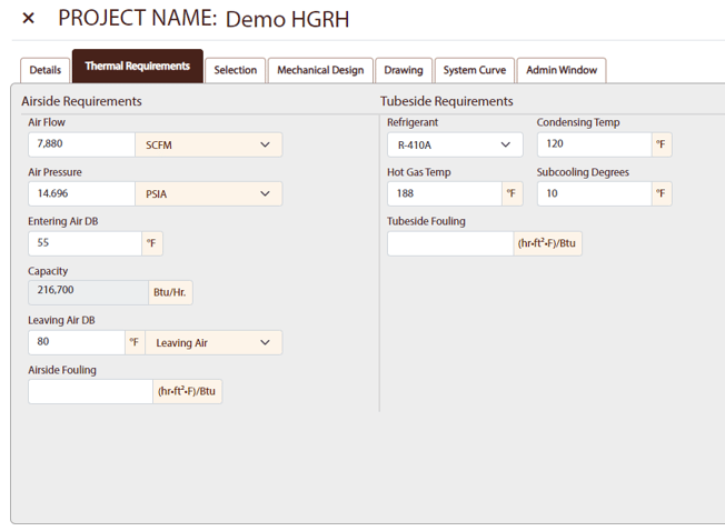
For this method, the first thing you’ll want to do is set your coil type to ‘condenser coil.’ This is because with the parallel condensing approach to designing a HGRH coil, we want the refrigerant to fully condense within the coil, after which it’s routed to the system’s expansion device.
Enter your performance data and select your refrigerant. In this case, again, we’re using R-410A. We’ll go with the standard 120F for our condensing temperature and a hot gas temp of 188F with 10F degrees of subcooling.
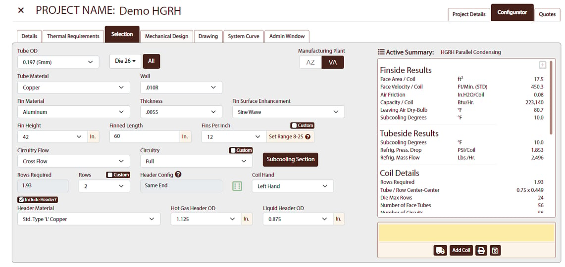
Since the goal is to fully condense the refrigerant, we can cut out some cost and size by using a small-OD tube construction, in this case 5mm. This design will cause an increase in pressure drop, but if the number of circuits in the coil is within reason, it shouldn’t cause any issues. We’ll go ahead and make that selection, choose our fin pattern (sine wave), 12 fins per inch, with the coil’s dimensions at 42" x 60".
After adding those inputs, if the results all appear within reason for your system, you’re good to go.
In summary, the addition of a hot gas reheat coil into your system presents an opportunity to lessen a unit’s electricity consumption by eliminating the need for resistance heating elements to recondition air as it enters a space. While there is an upfront cost associated with HGRH coils, it’s a cost that can usually be easily recouped over the life of the unit.
If you’re an OEM looking to adjust your unit design and are considering adding HGRH, drop us a line. We can work with you to make sure you’ve got the right design method for your application and can provide some more detail on best practices when running selections in our software.
Don’t get left out in the cold when it comes to heat transfer information. To stay up to date on a variety of topics on the subject, subscribe to The Super Blog, our technical blog, Doctor's Orders, and follow us on LinkedIn, Twitter, and YouTube.
If you're in the market for heat exchangers, let's work together to get you just the right tool for the job.