An 800MW 2x1 combined-cycle power plant in Alberta, Canada was experiencing consistent frost issues on anti-icing coils in their gas turbine inlet filter houses. The purpose behind these coils is to bring the temperature of the air up to just above the dew point, to prevent the condensation of water (which can cause serious damage through icing if introduced into the turbine.)
The chronic freezing was causing severe air pressure drop through the coils. This was creating a bottleneck in the power plant’s electricity production and the power facility was considering producing 30% less electricity if the problem were not resolved.
Over the course of two years, the power plant battled severe ice and snow fouling on other components of their inlet filter housing as well.
Frost and ice were building up on inlet bird screens, which was causing the screens to fall to the ground. Ice fouling was also affecting the leading edge of drift eliminators, contributing to the system’s pressure drop issues as well. So too was the accumulation of ice and frost on the leading edge of the inlet house’s glycol heating coils.
Plant personnel tried several remediation methods, but the problem persisted. The bird screens and drift eliminators were removed in 2016 in an unsuccessful attempt to reduce the fouling. Next, plant engineers installed pre-pre-filter curtains, which were also unsuccessful.
Like what you're reading? Subscribe to our blog and never miss a post!
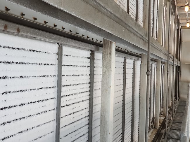
Power plant's original anti-icing coils
Various other as-needed mitigation efforts were also employed, including maintaining operation of the inlet glycol heating system throughout the winter months regardless of ambient temperature or humidity. These efforts included the manual removal of ice and snow from the glycol coils, which put personnel safety at risk, adding to the plant’s urgency to find a solution.
What was the root cause?
It was determined that there were two pieces to the power plant’s fouling woes – one was a quirk of the plant’s layout, and the other had to do with the temperatures on the anti-icing coil’s surface.
The inlet filter houses were situated near the plant’s cooling towers. Water vapor from these towers was drifting over to the houses and due to the amount of air that was entering the system, the vapor was being pulled into the airstream and causing the formation of the ice and snow. While not necessarily ideal, this dynamic wouldn’t have been a major problem if the anti-icing coils were serving their intended purpose.
While learning of the vapor from the cooling towers shed some light as to the severity and regularity of the fouling issues, engineers were left hunting for the reason behind the coil’s poor performance.
Since neither moving the cooling towers nor the inlet filter houses were possible, the plant commissioned an engineering study – of which SRC was a part. The goal was to determine the origin of the problem after deciding their existing anti-icing coils were inadequately designed and needed to be replaced. They posited that a change in fin material from stainless steel to aluminum had the potential to solve the issue, but they wanted to truly understand why.
At first, they believed the fouling was the result of simply needing more heat transfer from the tubes out to the edge of the fins, despite running 200°F glycol through the coil. This was certainly true, but there were additional factors at play.
What was our solution?
One of our first orders of business was to run coil ratings in our coil selection software. We started by running ratings according to the original coil’s construction (3-row, with stainless steel fins and tubes). We then compared those ratings to a copper tube/aluminum fin design. What we found was that we could meet the performance requirement (leaving air temperature) of the application using a 2-row design with copper tubes and aluminum fins.
We knew we could be onto something, but knowing the headache that the original coils had been to for the customer, we wanted to be absolutely certain that our proposed coil would solve the problem. Just because our software showed the theoretical coil would provide adequate leaving air temperature and provide the proper BTU/hr. didn’t mean it would work in practice (as the power plant was painfully aware). So, we wanted to understand the proposed coil’s performance on a deeper level than macro, overall performance data.
To accomplish this, we went granular, examining the level of heat transfer that was happening on the fin surface all along the tube at various spots throughout the coil.
Our engineers then put their heads together and wondered how the issue could be related to the way in which frost forms. Rather than forming in the air, frost instead forms upon contact with a cold surface. So, in theory, if the surface of the fin – which is where the frost was forming on the original coil – is warm enough, no frost.
So, we turned to our engineering technology, specifically our “segment” program, which allows us to analyze coil performance using finite analysis methodology. With this tool, we were able to look at the original coil alongside our proposed coil to look at the temperature of the fins at various places throughout the coil. What we found was that fin surface temperature was below freezing at most operating conditions, even with the hot glycol stream. This meant that as soon as any moisture hit the fin surface, frost would form, regardless of the temperature of the fluid within the coil’s tubes.
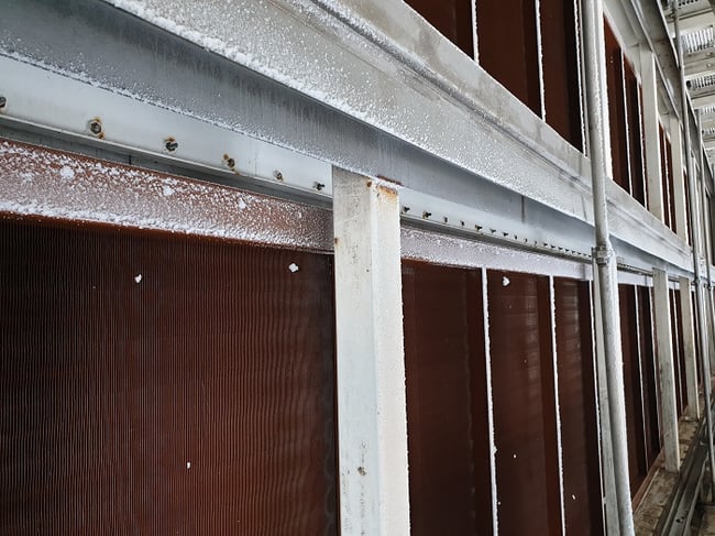
SRC's replacement anti-icing coils
On the other hand, our proposed aluminum fins were above freezing, even with the same fluid and air conditions. The explanation for this is fairly simple – stainless steel is a poor conductor of heat, and the heat provided by the glycol stream was rapidly dissipating and not emanating all the way out to the part of the fin where the frost was forming.
Benefits to the customer
The aluminum provided better thermal conductivity that was more even, so the temperature across the fins was more uniform, and therefore able to consistently maintain temperatures above freezing. We also included the added step of coating the coil in Heresite, to fortify the coil against potential corrosion.
Not only was the Cu/Al coil more effective from a heat transfer perspective, it’s also a lower-priced option, so the customer was able to save some money too. Another indirect cost benefit was that the plant didn’t have to reduce its output, nor did it have to continue sending workers out to clear the fouling in dangerous conditions.
Don’t get left out in the cold when it comes to heat transfer information. To stay up to date on a variety of topics on the subject, subscribe to The Super Blog, our technical blog, Doctor's Orders, and follow us on LinkedIn, Twitter, and YouTube.Need someone who understands your language? Simply answer a few questions and we’ll get our engineers on it.